Connell Model A
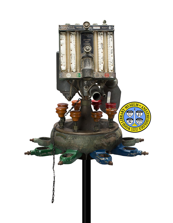
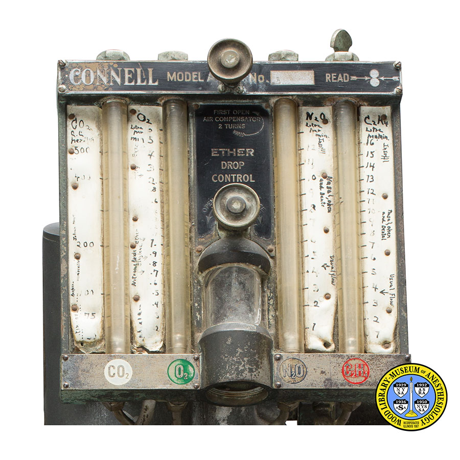
Karl Connell, M.D. (1878-1941), was a New York surgeon who designed his first anesthesia apparatus in 1908. His career later shifted to the manufacture of anesthesia machines. He filed to patent his “Model A” in 1931. It introduced upright, metric scales that registered the flow of each gas with a pair of ball bearings, and boasted accuracy “to the teaspoonful.” This flowmeter design set a new standard in the industry, which is still in use today. Shown here is the prototype, with hand-labeled scales for oxygen, nitrous oxide, ethylene and either carbon dioxide or acetylene. The machine also administered ether.
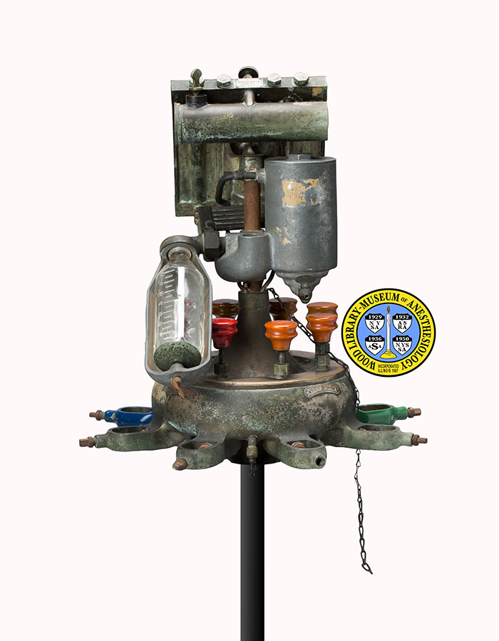
Although it used several flammable agents, the Model A was advertised as “the explosion proof machine”. It came equipped with a built-in humidifier that drew water from a glass nursing bottle. Absent from this prototype is the rebreathing bag. It was mounted high above the gas cylinders, with a valve that was intended to provide some control over the amount of rebreathing and breathing system pressure. This valve was also designed to keep the bag moist. Dr. Connell later served on an expert panel that studied the prevention of anesthetic explosions.
Catalog Record: Connell Model A
Access Key: amvg
Accession No.: 434
Title: Connell Model A.
Author: Connell, Karl Albert, 1878-1941.
Corporate Author: Connell.
Publisher: Astoria, N.Y.C. : Beard Machine Co., [1931?].
Physical Descript: 1 anesthesia machine : metals, glass, wood, rubber, paint ; 48.5 x 44.5 x 44.5 cm.
Subject: Anesthesia Machines.
Subject: Anesthesia, Inhalation – instrumentation.
Subject: Ethylene.
Subject: Nitrous Oxide.
Subject: Ether, Ethyl.
Note Type: Citation
Notes: Connell filed for a patent for this machine on October 21, 1931. Because this
machine is numbered, “No. 1”, has handwritten flowmeter scales, and the
manufacturer’s plate is marked with “PATENTS APPLIED FOR”, the year of
manufacture is likely to be 1931. The date range could change if
documentation or expert opinion indicate the range should be corrected.
Note Type: Citation
Notes: Dr. Connell dies after short illness. Scarsdale Inquirer. Friday, October 24,
1941;39:17. https://news.hrvh.
org/veridian/cgi-bin/senylrc?a=d&d=scarsdaleinquire19411024.2.187. Accessed
November 24, 2015.
Note Type: Citation
Notes: Connell, Karl [Albert]. The National Cyclopaedia of American Biography. Vol.
31. New York: J.T. White; 1944:240-241.
Note Type: Citation
Notes: Connell, Karl Jr. Biography on an Inventor: Dr. Karl Connell. [Naples, Fla.]:
Wintoon Waters, [2008]:17-23, 118-126.
Note Type: Citation
Notes: Connell K, inventor. Flow gauge. U.S. patent 1,965,333. July 3, 1934.
https://www.google.com/patents/US1965333. Accessed November 24, 2015.
Note Type: Citation
Notes: Connell K, inventor. Method and apparatus for the administration of gases. US
patent 2,073,194 A. March 9, 1937. https://www.google.ms/patents/US2073192.
Accessed November 20, 2015.
Note Type: Citation
Notes: A New Anaesthetic Apparatus: The New Connell Model A. Astoria, New York City:
The Scientific Apparatus Co.; [between 1931 and 1940?]. This is an undated 10
page marketing booklet.]
Note Type: Citation
Notes: Scientific Anaesthesia: Description and Operation of The New Connell
Apparatus. Astoria, New York: Beard Machine Company; [between 1931 and 1940?]
[This is an undated 24 page manual that includes a description of the device
and some instructions for use and care.]
Note Type: Physical Description
Notes: [1] One anesthesia machine for the administration of ether, nitrous oxide,
ethylene, carbon dioxide and oxygen; This description is based on the
perspective of a user facing the front of the device, i.e. “left” is the
user’s left, “right” is the user’s right; The measurements were taken of the
device not on a stand; Starting at the top is a flowmeter board; It is angled
at about 30 degrees; Across the front of the top of the flowmeter board are
the following markings; “CONNELL MODEL A”; This is followed by a turn knob
for the “AIR COMPENSATOR”; After the turn knob is, “No. 1” and “READ”;
Immediately after the word “READ” is an illustration of how to read the
flowmeters – arrows point to the invisible line between two flowmeter balls;
There are flowmeters for four gases; From left to right these are marked
“CO2” (in a white colored circle), “O2” (in a green circle), “N2O” (in a
black circle) and “C2H4” (in a red circle); The flowmeters are dry with two
balls; The increments for all of the flowmeters are marked in black ink by
hand; The increments for CO2 are marked and numbered at 0, 75, 100, 200, 400,
500; This cataloger was unable to read the small handwriting to the left of
the scale; The increments for O2 are marked and numbered with three different
scales; Starting from the bottom with .2, .3, .4, .5, .6, .7, .8, .9, 1.0, .1
.2, .3, .4, .6, .8, 2, 3, 4, 5, 6; Some handwritten words to the left of
this scale include, “Nitrous Oxide”, with an arrow pointing to the .7
increment, “Ethylene” with an arrow pointing to the .9 increment, and “Ether”
pointing to the 1.0 increment; Between the oxygen and nitrous oxide
flowmeters are two turn-knobs, and a drip chamber, for ether; The upper turn
knob is the one located between the text, “MODEL A” and “No. 1”; Just below
this knob, the flowmeter board is marked with, “FIRST OPEN [next line] AIR
COMPENSATOR [next line] 2 TURNS”; To the right of this text an arrow
indicates the direction that the knob should be turned; Below this, and just
above the turn-knob for the drip chamber, is the following text, “ETHER [next
line] DROP [next line] CONTROL”; To the left and right of the knob are arrows
indicating the direction to turn with the text “OPEN” (on left) and “CLOSE”
(on right); The drip chamber has an exterior glass wall; The increments for
the N2O flowmeter are marked and numbered at 1, 2, 3, 4, 5, 6, 7, 8, 9, 10,
11, and 12; To the right of the increments are some handwritten words; These
include “Insuffl” written near the number 12, “Nasal, open and Dental”
between numbers 8 and 10, and “Usual flow” with an arrow pointing just above
the number 4; The increments for the C2H4 flowmeter are marked and numbered
at 1, 2, 3, 4, 5, 6, 7, 8, 9, 10, 11, 12, 13, 14, 15, and 16; To the right of
the increments are some handwritten words; These include “Insuffl” written
near the numbers 15 and 16, “Nasal, open and Dental” between numbers 7 and 10
and “Usual Flow” with an arrow pointing to just below the number 4; A metal
plate is affixed to the top center of the flowmeter board; It is marked with
the following: “MFG. BY [new line] BEARD MACHINE CO. [new line] ASTORIA, N.Y.
C. [new line] PATENTS APPLIED FOR”; On the back of the flowmeter board, just
below the top, a metal tubular reservoir for liquid ether is affixed in a
horizontal position; The end of the reservoir on the right side is glass to
allow visualization of the level of the liquid ether; Below the reservoir, on
the left, is an all metal gas humidifier; A spout to drain the humidifier
extends from the bottom of the humidifier toward the back; On the right in
back is a glass bottle reservoir for the humidifier; A metal ‘cradle’ holds
the bottle in place; The bottle is embossed with the text, “PYREX” and
incremental lines at half ounce points from .5 to 8 ounces; … [continued at
2].
Note Type: Physical Description
Notes: [2, continued from 1] … The increments are numbered at whole numbers from 1
to 8; A large connection for tubing to the patient mask extends forward, just
below the flowmeter board on the right; To the right of the breathing system
connection is a smaller port to connect tubing for fresh gas flow to the
patient mask; Behind and just below the flowmeters, and between the
humidifier and bottle, is an opening for tubing that would have held the
reservoir bag and an adjustable spill valve; These items are not with this
machine; Just behind and slightly below the flowmeter board, and below and in
front of the humidifier is piece that this cataloger was unable to identify;
Possibly the ether vaporizing coil described in the Model A literature, it is
rectangular and appears to be composed of four long narrow tubes held
together in a flat rectangular shape; All of the items described thus far are
held above the reducing valve and yoke system; The reducing valves are held
in what Dr. Connell described as “a metallic bowl of tough bronze supporting
8 gas-tank yokes” (From the Scientific Anaesthesia booklet with the Beard
Machine Company printed on the title page); Dr. Connell also described this
bowl as being, “in the nature of a water radiator in which are immersed the 8
reducing valves.”; An opening, or hole, possibly for adding water to the
‘bowl’ is located on the front of the bowl, just behind the the turn-knobs;
Each yoke has a turn knob; There are two yokes and turn-knobs for each gas;
They are labeled with a metal plate located between the yoke pairs; Beginning
at the front left, the two yokes are painted green and the text on the
plate-label between them is “OXYGEN”; The back left pair are labeled “CARBON
DIOXIDE”; The back right pair are labeled “ETHYLENE”, and the two knobs for
ethylene are red in color; The remainder of the knobs are an orange-brown
color; The front right pair of yokes are painted blue and labeled “NITROUS
OXIDE”; Between the carbon dioxide and ethylene yokes is a downward port or
spout, possibly for draining water from the ‘bronze radiator chamber’.
Note Type: Reproduction
Notes: Photographed by Mr. Steve Donisch, June 5, 2015.
Note Type: Exhibition
Notes: Selected for the WLM website (noted November 20, 2015).
