McCurdy Machine
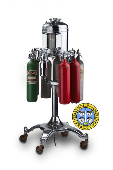
The Safety Anaesthesia Apparatus Concern, of Chicago, made anesthesia machines from the 1910s to the 1950s. The McCurdy machine was named for the President of the company, who may have designed it. It held two cylinders each of nitrous oxide, oxygen, carbon dioxide, and the explosive gas, ethylene. The company claimed that the machine maintained a high enough level of humidity to prevent static sparks, making grounding equipment unnecessary. The large lever was used to turn the machine on and off. The knobs on the top of the dome were used to control the “dose” of each gas, which was registered on the inset flowmeters. An unusual feature was the regulating dial on the carbon dioxide absorber, which was used to provide “perfect control” over the patient’s rate of respiration, and thus the “degree of relaxation” (the depth of anesthesia). The Model A, shown here, could accommodate cylinders of small or medium size. The Model B was mounted on a cart that could hold larger tanks.
Catalog Record: McCurdy Machine
Access Key: akxm
Accession No.: 2013-09-06-4
Title: Safety gas oxygen apparatus: McCurdy Model / Safety Anaesthesia Apparatus
Concern.
Corporate Author: Safety Anaesthesia Apparatus Concern.
Title variation: Alt Title
Title: McCurdy machine.
Publisher: Chicago, Illinois : Safety Anaesthesia Apparatus Concern, [between 1931 and
1950?].
Physical Descript: 1 anesthesia machine : metals, plastics, glass, rubber : 128 x 70.5 x 83.5 cm.
Subject: Ethylene.
Subject: Anesthesia Machines.
Subject: Nitrous Oxide.
Subject: Carbon Dioxide Absorbers.
Subject: Oxygen.
Note Type: General
Notes: The early year in the date range for the possible year of manufacture is
based on the date of the earliest publication in which the McCurdy Model is
referenced (an advertisement for the McCurdy Model in Hospital Management,
1932, volume 32). The late date is an estimate based on the time when a
number of authors report that cyclopropane had largely replaced ethylene
(Jacob AK, Kopp SL, Bacon DR, Smith HM, 2013 ; Jones R, 2014 ; Sixty-six
years ago in Anesthesia & Analgesia, 1989). The date range could change if
documentation indicates that it should be corrected.
Note Type: General
Notes: The title is taken from a faded metal plate on the stand of the apparatus;
This title is reflected in the booklet with the cover title, “Safety Gas
Oxygen Apparatus.”
Note Type: With
Notes: A specialized kind of wrench accompanied this machine; It measures 2 x 17.5 x
11 cm.
Note Type: Citation
Notes: Instruction for operating The McCurdy Model Safety Gas-Oxygen Apparatus. [A
five page, unpublished, type written document sent to Paul M. Wood with a
letter by D.G. McCurdy dated June 21, 1935.] WLM Company Files. Located at:
Wood Library-Museum of Anesthesiology, Schaumburg, Illinois.
Note Type: Citation
Notes: Jacob AK, Kopp SL, Bacon DR, Smith HM. The history of anesthesia. In: Barash
PG, Cullen BF, Stoelting RK, Cahalan MK, Stock MC, Ortega R, eds. Clinical
Anesthesia. 7th ed. Philadelphia: Wolters Kluwer/Lippincott Williams and
Wilkins; 2013:13. [Page 13, “When cyclopropane was introduced, ethylene was
abandoned..”].
Note Type: Citation
Notes: Jones R. A history of inhaled anesthetics. :In: Eger EI II, Saidman LJ,
Westhorpe RN, eds. The Wondrous Story of Anesthesia. New York: Springer;
2014:616-617.
Note Type: Citation
Notes: Safety gas oxygen apparatus: McCurdy Model “A”. Chicago, Illinois: Safety
Anaesthesia Apparatus Concern; [1931-1940]. [This is a company booklet
printed without a date. Because it refers to the McCurdy Model as ‘new” the
date it was printed is estimated to be before the 1940s.]
Note Type: Citation
Notes: Sixty-six years ago in Anesthesia & Analgesia. Anesth Analg. 1989;68(3):405.
https://journals.lww.
com/anesthesia-analgesia/Citation/1989/03000/Sixty_Six_Years_Ago_In__Anesthes
a___Analgesia_.44.aspx. Accessed September 2, 2014.
Note Type: Physical Description
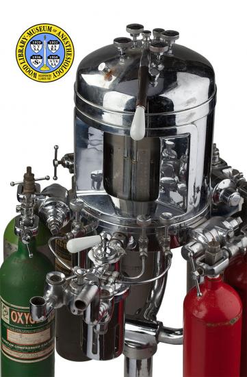
Notes: One anesthesia machine with a cylindrical center surrounded by four units for
a single gas; Each unit has two yolks for gas cylinders; The measurements
were taken facing the front of the machine; Facing the machine and moving
clockwise from the left is the unit for oxygen, followed by carbon dioxide,
then nitrous oxide, and then ethylene; On the top of the machine is a
‘percentage control’ turn knob for each gas; Left front is the knob for O2,
left rear is the knob for CO2, right rear N2O, and right front ethylene;
Behind the CO2 and N2O percentage control valves is a water intake port to
the mixing chamber; A long ‘central control’ lever is attached to the center
of the top of the machine; It can be moved between a knob labeled “OFF” on
the top of the machine in front of the O2 knob, and a knob labeled “ON” on
the top of the machine in front of the ethylene knob; On the front of the
machine is a glass viewing plate to four water level tubes; There are two
medal scales, each with a water level tube on the left and right; Both metal
scales are marked with different increments on the left and right; The left
of both metal scales is marked in increments of 1 (with two exceptions: 2.5
and 33.5), from zero at the top to 33..5 at the bottom; The increments are
numbered at 0, 2.5, 5, 10, 15, 20, 25, 33.5; The right of both metal scales
are marked in increments of 10 from 0 to 100; The increments are numbered
from 0 to 100 in increments of 10 including the 0 starting tic mark; The
embossed gas labels in the scale are difficult to read but are located above
the zero marks, and from left to right are, “OXYGEN”, “ETHYLENE”, “DIOXIDE”,
and “OXIDE”; An ether vaporizer is connected to the front of the machine; On
top of the vaporizer is an ether control turn valve with an arrow that can be
pointed to any of eleven increments between, “ETHER,” on the left and, “BASIC
GASES,” on the right; A curved line from the bottom of the fist increment on
the left to the top of the first increment on the right provides a general
illustrative representation of the percentage of ether as compared to the
other gases; Just after the vaporizer control valve is a connection for the
breathing system; Three tubes run from the front of the machine to the sides
of the connection: The one on the left is an oxygen flush valve, and the two
on the right are an ethylene force valve and a N2O force valve; The
inspiratory and expiratory connections for the breathing circuit come next;
On the left are connections for the carbon dioxide absorber and on the right
for the inspiratory tubing and the breathing bag (a carbon dioxide absorber,
respiratory tubing, Y-tube, and breathing bag are not with this machine, but
are pictured in the companies booklet on the McCurdy Model); Between the
inspiratory and expiratory sides of the breathing circuit connection is a
ventilating turn-valve which can be turned to OFF or ON; The bottom of the
machine is supported on a four legged pole by three supporting bars; Most of
the machine, its parts and the pole are nickel- or chrome-plated; On the pole
below were the bars meet, is a manufacturers plate that is faded; The text
on the label includes, “SAFETY GAS-OXYGEN APPARATUS [new lie]McCURDY MODEL NO
108 [new line] PATENT PENDING [new line] SAFETY ANAESTHESIA APPARATUS [new
line] CONCERN [new line] CHICAGO ILLINOIS”; The four legs of the pole are
on wheels.
Note Type: Reproduction
Notes: Photographed by Mr. Steve Donisch, September 20, 2013.
Note Type: Historical
Notes: The Safety Anaesthesia Apparatus Concern, of Chicago, made anesthesia
machines from the 1910s to the 1950s. The McCurdy machine was named for the
President of the company, who may have designed it. It held two cylinders
each of nitrous oxide, oxygen, carbon dioxide, and the explosive gas,
ethylene. The company claimed that the machine maintained a high enough level
of humidity to prevent static sparks, making grounding equipment unnecessary.
The large lever was used to turn the machine on and off. The knobs on the top
of the dome were used to control the “dose” of each gas, which was registered
on the inset flowmeters. An unusual feature was the regulating dial on the
carbon dioxide absorber, which was used to provide “perfect control” over the
patient’s rate of respiration, and thus the “degree of relaxation” (the depth
of anesthesia). The Model A, shown here, could accommodate cylinders of small
or medium size. The Model B was mounted on a cart that could hold larger
tanks.
Note Type: Exhibition
Notes: Selected for the WLM website.
